1
   

Rick's electronic projects


Reply Sun 24 Aug, 2003 01:04 pm
For all of you that don't already knoe, my name is Rick. Anyone I am going to use this thread to post plans of electronics I have made.

Modular Burglar Alarm

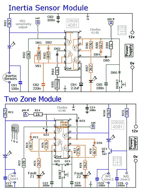
This circuit features automatic Exit and Entry delays and a timed Bell Cut-off. It has provision for both normally-closed and normally-open contacts, and a 24-hour Personal Attack/Tamper zone. It is connected permanently to the 12-volt supply and its operation is "enabled" by opening SW1. By using the expansion modules, you can add as many zones as you require; some or all of which may be the inertia (shock) sensor type. All the green LEDs should be lighting before you open SW1. You then have up to about a minute to leave the building. As you do so, the Buzzer will sound. It should stop sounding when you shut the door behind you. This indicates that the Exit/Entry loop has been successfully restored within the time allowed. When you re-enter the building you have up to about a minute to move SW1 to the off position. If SW1 is not switched off in time, the relay will energise and sound the main bell. It will ring for up to about 40 minutes. But it can be turned off at any time by SW1. The "Instant" zone has no Entry Delay. If you don't want to use N/O switches, leave out R8, C8 and Q2; and fit a link between Led 3 and C7. The 24 Hour PA/Tamper protection is provided by the SCR/Thyristor. If any of the switches in the N/C loop is opened, R11 will trigger the SCR and the bell will ring. In this case the bell has no time limit. Once the loop is closed again, the SCR may be reset by pressing SW2 and temporarily interrupting the current flow. The basic circuit will be satisfactory in many situations. However, it's much easier to find a fault when the alarm is divided into zones and the control panel can remember which zone has caused the activation. The expansion modules are designed to do this. Although they will work with the existing instant zone, they are intended to replace it. When a zone is activated, its red LED will light and remain lit until the reset button is pressed. All the modules can share a single reset button. The Stripboard layout of the prototype is available.
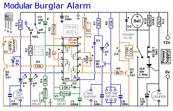
http://www.electro-tech-online.com/images/projects/modular_burglar_alarm1.gif

http://www.electro-tech-online.com/images/projects/modular_burglar_alarm2.gif
  • Topic Stats
  • Top Replies
  • Link to this Topic
Type: Discussion • Score: 1 • Views: 1,983 • Replies: 6
No top replies

 
jespah
 
  1  
Reply Sun 24 Aug, 2003 03:10 pm
Hey Rick,

I'm going to send this topic to my Dad who I think will be really interested in it.
0 Replies
 
safecracker
 
  1  
Reply Sun 24 Aug, 2003 03:15 pm
Right on O'm going to add a few more in a bit....this actually came from a buddy we designed it togather then I built it.
0 Replies
 
safecracker
 
  1  
Reply Sun 24 Aug, 2003 03:20 pm
Here's a simple lie detector that can be built in a few minutes, but can be incredibly useful when you want to know if someone is really telling you the truth. It is not as sophisticated as the ones the professionals use, but it works. It works by measuring skin resistance, which goes down when you lie.

http://www.electro-tech-online.com/images/projects/lie_detector.gif
0 Replies
 
jespah
 
  1  
Reply Sun 24 Aug, 2003 04:28 pm
Holy cannoli, verra nice!

Dad's a retired electronics/electrical engineer so you're definitely speaking his language so to speak.
0 Replies
 
safecracker
 
  1  
Reply Sun 24 Aug, 2003 04:32 pm
Right on you should get him to post here I could use the input
0 Replies
 
safecracker
 
  1  
Reply Sun 24 Aug, 2003 04:41 pm
5 Zone Alarm System

Each zone uses a normally closed contact. These can be micro switches or standard alarm contacts (usually reed switches). Zone 1 is a timed zone which must be used as the entry and exit point of the building. Zones 2 - 5 are immediate zones, which will trigger the alarm with no delay. Some RF immunity is provided for long wiring runs by the input capacitors, C1-C5. C7 and R14 also form a transient suppresser. The key switch acts as the Set/Unset and Reset switch. For good security this should be the metal type with a key. At switch on, C6 will charge via R11, this acts as the exit delay and is set to around 30 seconds. This can be altered by varying either C6 or R11. Once the timing period has elapsed, LED6 will light, meaning the system is armed. LED6 may be mounted externally (at the bell box for example) and provides visual indication that the system has set. Once set any contact that opens will trigger the alarm, including Zone 1. To prevent triggering the alarm on entry to the building, the concealed re-entry switch must be operated. This will discharge C6 and start the entry timer. The re-entry switch could be a concealed reed switch, located anywhere in a door frame, but invisible to the eye. The panic switch, when pressed, will trigger the alarm when set. Relay contacts RLA1 provide the latch, RLA2 operate the siren or buzzer.

http://www.electro-tech-online.com/images/projects/5_zone_alarm_system.gif
0 Replies


Related Topics

Recording Detector - Question by gollum
Bad picture on my Sharp LCD TV - Question by hydroplant
LCD TV. Help! - Question by kolinos4
p3 or 360 and why - Question by XxGWOPBOYZxX
Post your latest gizmos - Discussion by Chumly
IPOD OR ZUNE HD? - Discussion by detroittou
Giving up my iPod for a Walkman - Discussion by djjd62
Digital audio in your home sound system - Question by hingehead
 
  1. Forums
  2. » Rick's electronic projects
Copyright © 2025 MadLab, LLC :: Terms of Service :: Privacy Policy :: Page generated in 0.03 seconds on 01/02/2025 at 07:25:55